

.webp "Dual flow meter with display")
.webp "Dual air flow meter with display")
.webp "Dual air flow sensor with display")

EU declaration conformity
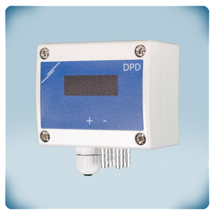

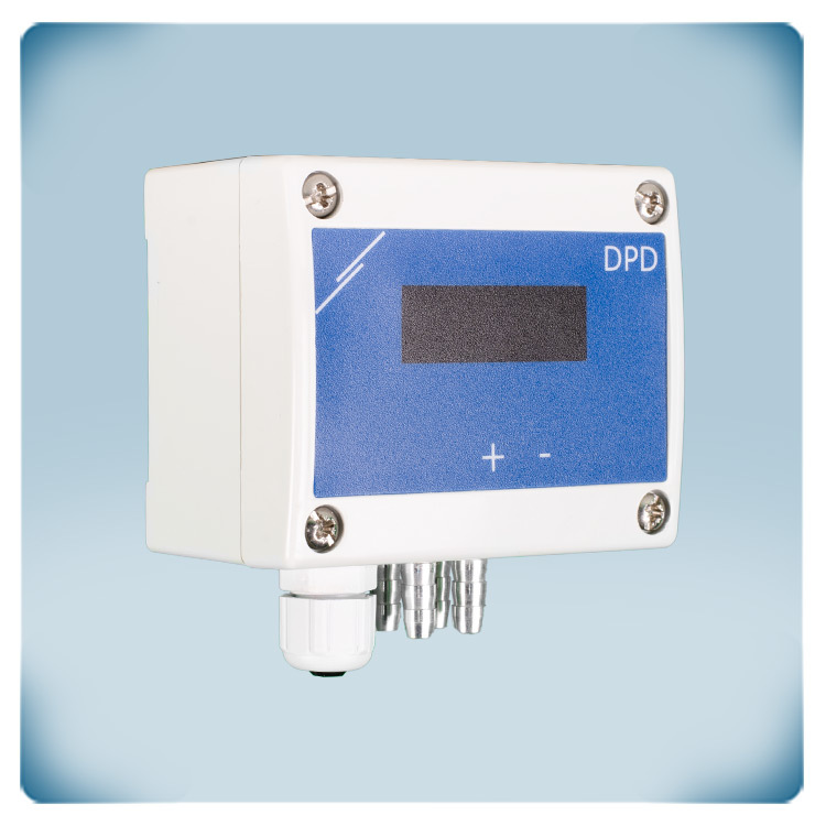
Dual Differential Pressure Sensor | Display | 0–2000 Pa | 24 VAC-VDC
Product description
DPD-G-2K0 is a sensor for simultaneously measuring differential pressure at two different locations. In addition, air volume flow and air velocity can be calculated.
The sensor features a 7-segment LED display, has two analogue outputs and operates on a 24 VAC or 24 VDC power supply. All measured values and settings are accessible via Modbus RTU communication.
The enclosure is made of premium plastic and provides an IP65 protection. The sensor is designed for wall-mounting.


Additional specifications and description
Which parameters are measured and why is it important?
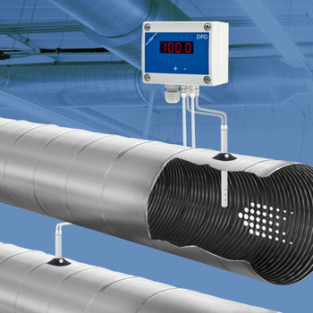
This sensor simultaneously measures differential pressure [Pa] at two different locations. Based on this measurement, air volume flow [m³/h] or air velocity [m/s] can be calculated. To enable these calculations, optional connection sets are required.
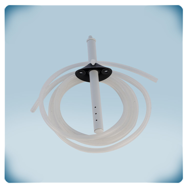
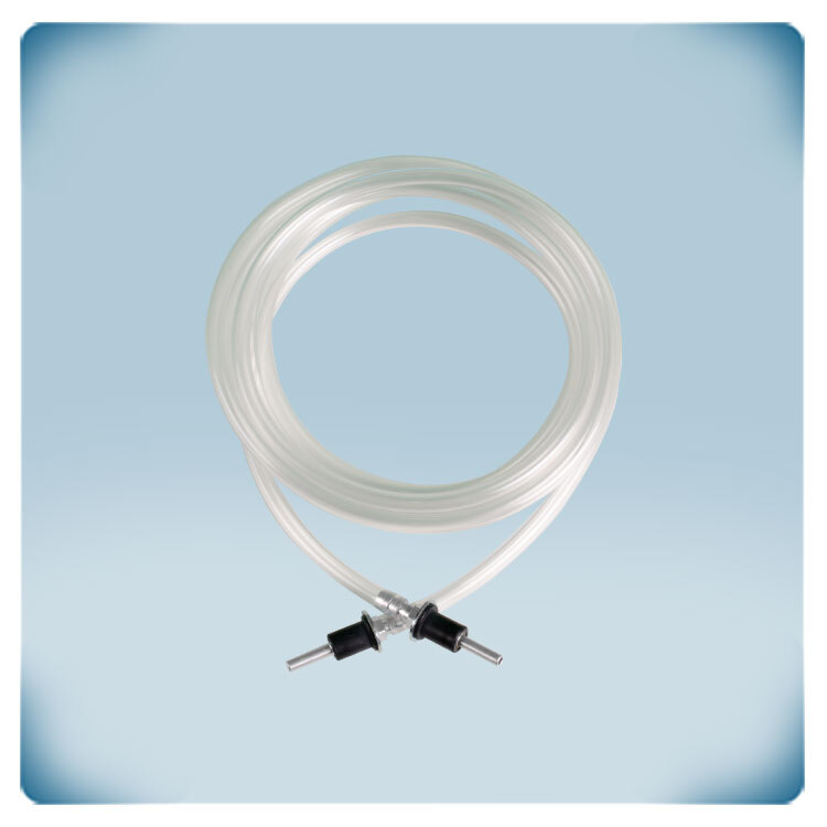
Set types PSET-PVC-200 or PSET-QF-200 can be used to measure differential pressure, or air volume flow based on the K-factor of the fan.
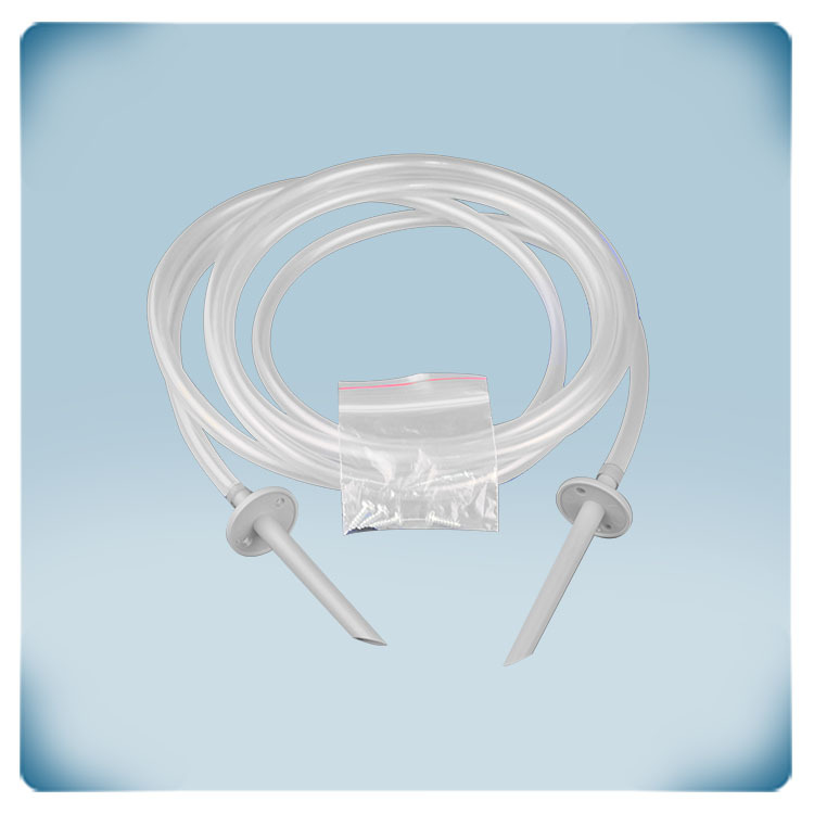
Set types PSET-PTS-200 or PSET-PTL-200 can be used to measure air velocity, or air volume flow based on the cross section of the duct.
Differential pressure is a key parameter for optimising ventilation system performance. Maintaining the correct differential pressure ensures proper airflow, improves indoor air quality and comfort, and supports optimal energy efficiency. This sensor's dual functionality makes it ideal for simultaneously monitoring supply and extract air volume flow in ventilation systems or Heat Recovery Units (HRUs).
 What are the configuration and customisation options?
This sensor has two analogue outputs that transmits the measured differential pressure, air volume flow or air velocity proportionally. Different output types are available, including 0–10 VDC, 0–20 mA, 0–100% PWM. By default, the sensor measures differential pressure within the range of 0–2000 Pa. The output transmits 0 V at 0 Pa and 10 V at 2000 Pa. The range, the output type and all other settings can be adjusted via Modbus RTU.
The 7-segment LED display visualises the two values. The display can be disabled via Modbus RTU.
The sensor can be connected to internet via a Sentera internet gateway, which makes it possible to log data or to adjust settings remotely.
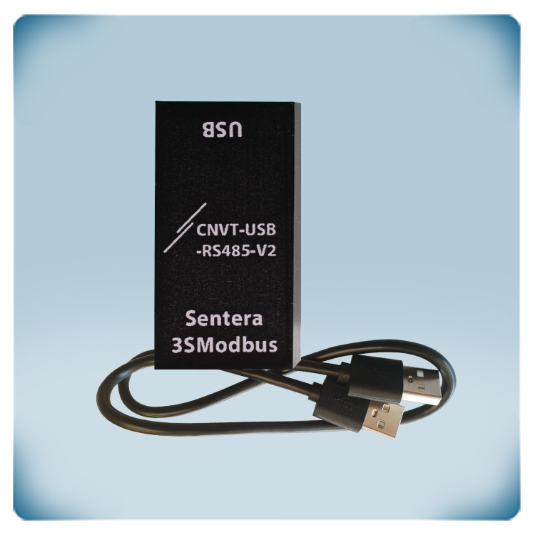
Modbus RTU communication is used to transmit the measured values and can be used to change all of the settings. The Modbus register map provides a complete overview of all adjustable settings.
How is the sensor installed, and what are the power and connectivity requirements?
The sensor is intended for mounting on a wall.
The supply voltage is 24 VAC or 24 VDC. The ground terminals of the power supply (V-) and output (GND) are internally connected. This means that a 3-wire cable is required to connect this sensor. Make sure not to connect this common ground to other devices that are powered by a DC voltage. A 24 VDC supply voltage increases the safety and reliability of your installation, by offering protection against short circuit, overload and overvoltage.
The supply voltage, the analogue output and Modbus RTU communication can be connected via the screw clamp terminal blocks. They eliminate the need for routine maintenance and guarantee a reliable contact for solid or stranded wires.
What are the manufacturing quality and protection ratings?
All sensors are designed and manufactured in Europe. Each device is calibrated and tested in our factory. Only high-quality components are used, ensuring long-term stability and accuracy.
The enclosure is produced in-house by Sentera Plastics from grey premium ASA. This material is heat-resistant and provides exceptional strength and excellent protection against impacts. It offers an IP65 protection against ingress of dust and moisture. The pressure connection nozzles are made from aluminium.
Remarks, reviews & ratings