.webp "HVAC differential pressure sensor")
.webp "air flow sensor")
.webp "air flow meter")
.webp "air flow transmitter")
.webp "air flow detector")
EU declaration conformity


Differential pressure transmitter | 0 - 4000 Pa | PoM
Product description
This device measures differential pressure within a range of 0 to 4,000 Pa. It can also measure air volume flow or air velocity.
For simplified connection, it utilizes 24 VDC Power over Modbus (PoM), which connects both power and Modbus RTU communication through a single RJ45 socket.
Four LED indicators provide a visual display of the sensor's status and current readings. The differential pressure range and all other settings are fully adjustable via Modbus RTU.
Additional specifications and description
What Does the Sensor Measure and What Can It Calculate?
This sensor measures differential pressure [Pa]. Based on this measurement, air volume flow [m³/hr] or air velocity [m/s] can be calculated. To calculate air volume flow based on the K-factor of the fan, use the connection set type PSET-PVC-200 or PSET-QF-200. This connection set can also be used to measure differential pressure. To calculate air volume flow based on the duct cross section [cm²] or air velocity [m/s], use the connection set type PSET-PTS-200 or PSET-PTL-200. 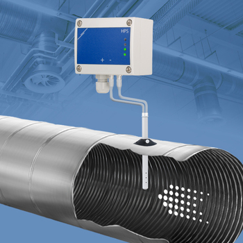
How Does the Sensor Provide Visual Status?
This pressure transmitter offers a clear, visual indication of the differential pressure level via the green, yellow and red LED. The green LED indicates that the pressure level is within range. When the pressure level enters the alert range, the yellow LED lights up. Red means: differential pressure out of range. The LEDs can also indicate the status of the air volume flow or air velocity. The second green LED indicates the sensor status. It is activated when power supply and Modbus RTU communication are enabled.
This pressure transmitter offers a clear, visual indication of the differential pressure level via the green, yellow and red LED. The green LED indicates that the pressure level is within range. When the pressure level enters the alert range, the yellow LED lights up. Red means: differential pressure out of range. The LEDs can also indicate the status of the air volume flow or air velocity. The second green LED indicates the sensor status. It is activated when power supply and Modbus RTU communication are enabled.
How Is the Sensor Powered and Connected?
One RJ45 connector is all it takes to connect this sensor! Modbus RTU communication and 24 VDC power supply are connected via one cable - we call it Power over Modbus or PoM. All measured values are available via Modbus RTU communication. To facilitate wiring, we recommend to use a Sentera 24 VDC power supply with RJ45 connector. These power supplies also offer protection against short circuit, overload and overvoltage. A 24 VDC supply voltage increases the safety and reliability of your installation.
One RJ45 connector is all it takes to connect this sensor! Modbus RTU communication and 24 VDC power supply are connected via one cable - we call it Power over Modbus or PoM. All measured values are available via Modbus RTU communication. To facilitate wiring, we recommend to use a Sentera 24 VDC power supply with RJ45 connector. These power supplies also offer protection against short circuit, overload and overvoltage. A 24 VDC supply voltage increases the safety and reliability of your installation.
What Are the Sensor's Quality and Durability Features?
The enclosure is made of high-quality r-ABS VO (UL94) plastic. This material is heat resistant, very tough and offers good protection against impacts. The pressure connection nozzles are made from Aluminum. The sensor enclosure offers an IP65 protection against ingress of dirt and water. This sensor can be wall-mounted.
The enclosure is made of high-quality r-ABS VO (UL94) plastic. This material is heat resistant, very tough and offers good protection against impacts. The pressure connection nozzles are made from Aluminum. The sensor enclosure offers an IP65 protection against ingress of dirt and water. This sensor can be wall-mounted.


Remarks, reviews & ratings