How to read out EC fan speed via Modbus RTU communication?
If the EC motor is equipped with a tachometer, the motor speed can be read with it. Most tachometers transmit the motor speed as a PWM signal.
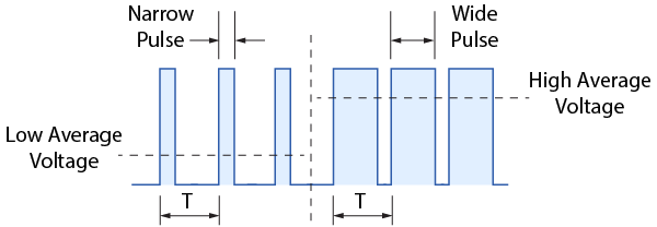
A PWM or Pulse Width Modulated signal looks like a continuous stream of electrical pulses. It is a control signal, comparable to an analogue 0-10 Volt or 0-20 mA signal. Like other analog signals, a PWM signal is also used to transmit information. For example, to communicate the desired speed to an EC motor. Or to transmit the desired position of a control valve.
A PWM signal is a continuous train of electronic pulses. The total time between two high pulses is always constant. This is called the pulse train frequency. The difference between a low and a high PWM signal lies in how long a high pulse lasts.
Typically, the EC fan speed will increase in proportion to the value of the analogue 0-10 VDC or 0-20 mA signal. For a PWM signal – a continuous train of electronic pulses consisting of a HIGH and LOW part - this works as follows:
Think of a PWM signal like turning a light switch ON and OFF very fast. Each time you turn the switch ON and OFF, that’s called a cycle. Now, the important part is: how long you keep the switch ON during each cycle — that’s called the duty cycle.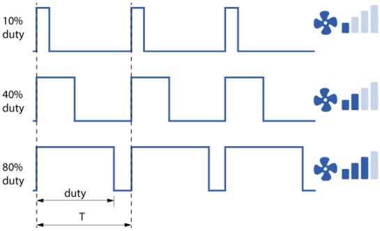
Duty Cycle = How Much Time the Signal Is ON
Imagine a 1-second period where:
• If the signal is ON for only a short time, say 10% of the second → the device (like a fan) runs slowly.
• If it’s ON for half the time (50%) → the fan runs at medium speed.
• If it’s ON almost all the time (100%) → the fan runs at full speed.
Even though the signal is just flipping ON and OFF, the device “averages” the signal over time and changes its speed or position based on how long it’s ON.
Frequency = How Fast It Switches
The frequency is how many ON/OFF cycles happen each second. The shorter the time per cycle (T), the more cycles you can fit into one second — so the higher the frequency. That’s why Frequency = 1 divided by T, where "T" stands for full cycle.
• Example: 1000 Hz = 1000 ON/OFF flips every second (so each cycle is very short – just 1 millisecond). The frequency needs to be fast enough so the device doesn’t see the flickering — it just responds to the average “power.”
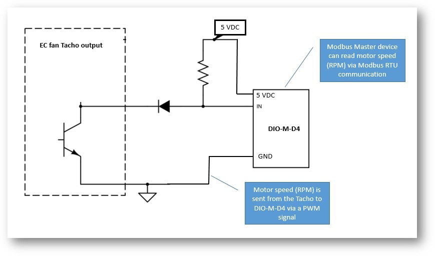
The height of these pulses is called the amplitude and is expressed in volts. If the tachometer is equipped with an open-collector output, the desired voltage can be supplied (e.g., 5 VDC). The tachometer's open-collector output can be thought of as a switch that allows or blocks the voltage at very high speeds.
Following wiring diagram offers a summary of all this: